
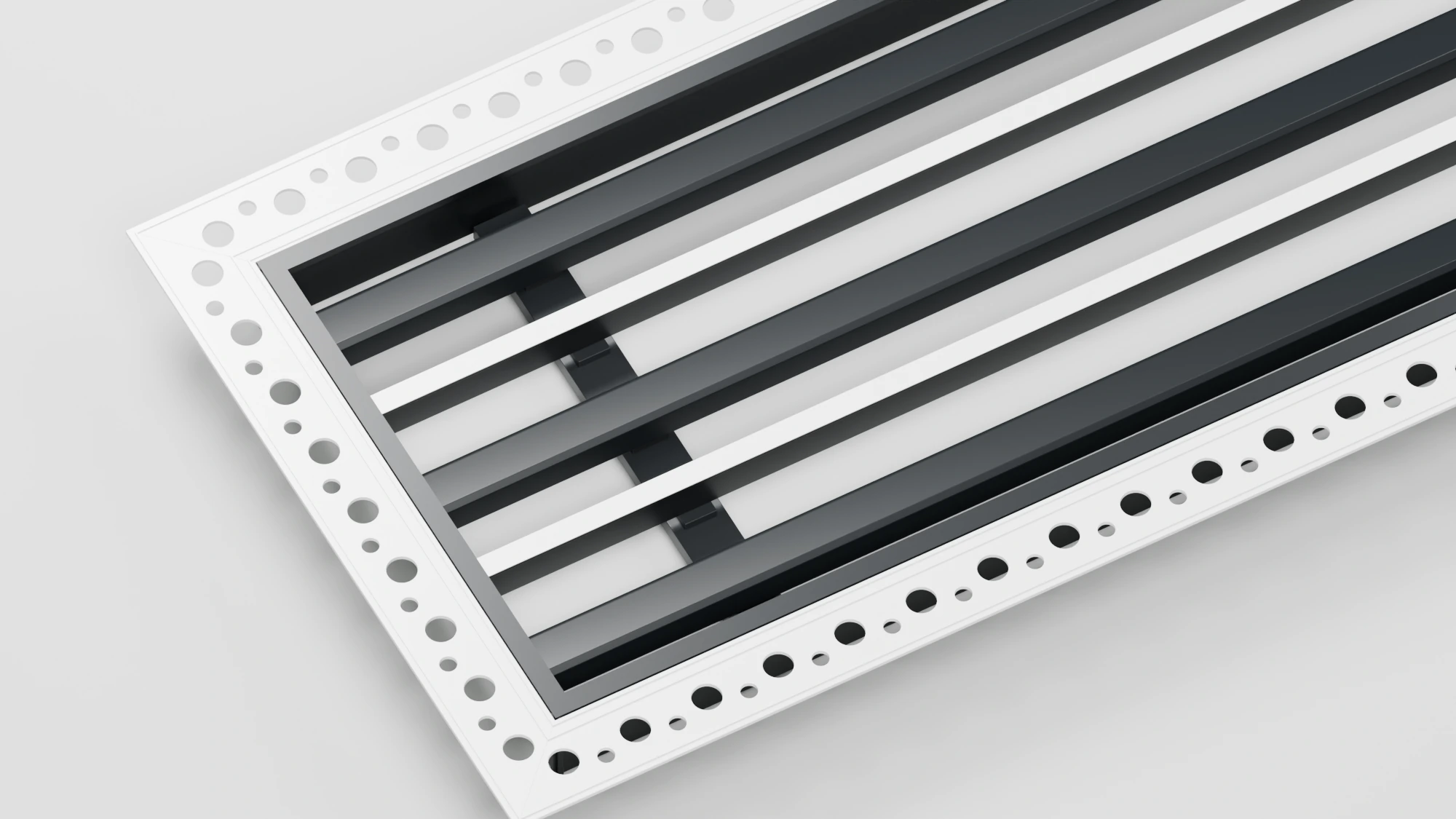
Reviewed 13 October 2026. A plaster-in diffuser needs to be coordinated with the ceiling before the opening is cut. The frame, board build-up, finished slot and maintenance access should be shown together on the project detail.
This guide sets out the information to confirm before ordering. Installation depth, fixing method and removable parts depend on the selected profile; the project drawing and product instructions take precedence over a generic sequence.
Confirm the frame and ceiling build-up
Identify the proposed frame, its plaster-in flange and the finished ceiling plane. Confirm the board thickness, supporting structure, opening dimensions, available depth and the junction between metal and ceiling finish. A frame that fits the visible opening may still conflict with the duct connection, lighting or structure above it.
A plaster-in flange is finished into the ceiling. It is not a substitute for a designed mechanical fixing. Agree supports and the joint treatment with the installer and ceiling-system supplier. Where a plenum is included, confirm its support and connection separately.
Illustrative section for a removable-core arrangement. It does not define a standard Hongyang installation depth, opening tolerance or fixing schedule. Confirm these on the drawing for the selected product.
Agree the installation sequence
- Coordinate the ceiling opening, supports, duct connection and adjoining finishes before fabrication.
- Check the supplied frame and components against the approved drawing before closing the ceiling.
- Install and align the frame using the specified supports and fixings.
- Protect the slot and accessible components during boarding, jointing, plastering and painting.
- Apply the agreed ceiling joint treatment and finish without obstructing the air path or retaining features.
- Where the design has a removable core, refit it after the finishes have cured and check that its retainers engage.
- Complete the specified cleaning, access and airflow checks with the installation team.
Delivery can be coordinated around the agreed construction sequence. Confirm whether the frame and core should arrive together or separately; two-stage delivery is not assumed for every order.
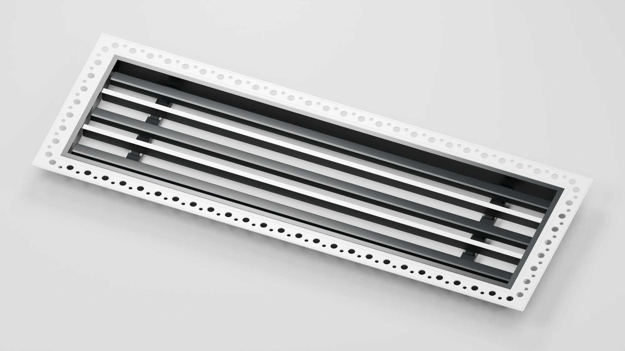
Keep active and blank sections clear on the drawing
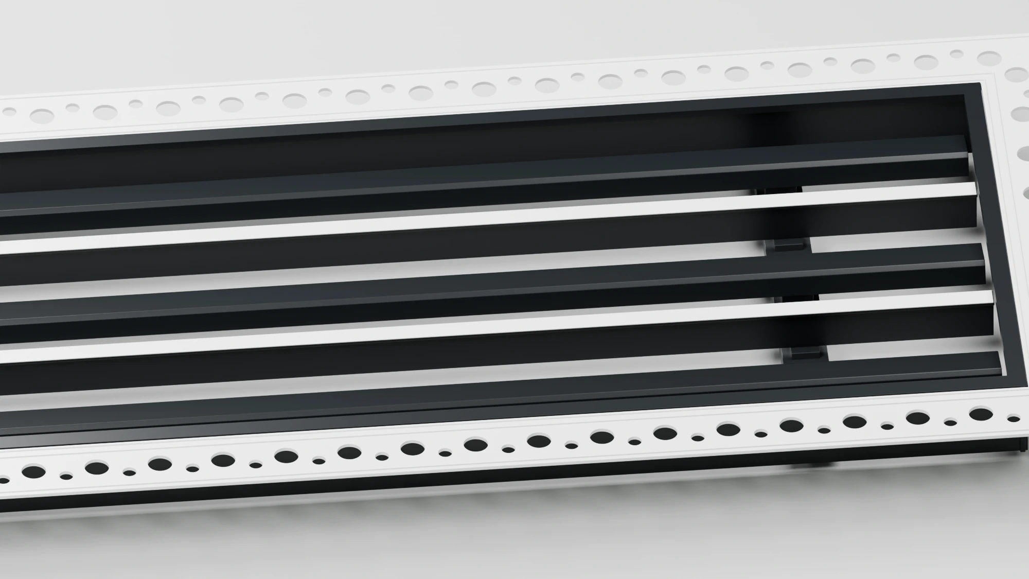
A continuous visual line may include active air sections and blank sections. Identify which is which, along with blade direction, backing treatment, joints and end conditions. Any blanking or dark backing must be compatible with the design and must not obstruct an active supply or return path.
Check maintenance access before choosing the detail
Do not assume every plaster-in core, corner or individual blade is removable. Confirm the removal method, clearance and retaining arrangement for the actual model. Where equipment behind the ceiling needs servicing, coordinate a suitable access route rather than assuming the diffuser opening will provide it.
Frequent cleaning does not automatically rule out plaster-in construction, but access needs to be demonstrated. A sample or section review can help the project team assess whether the selected detail works with its maintenance plan.
What to send with your enquiry
- Opening length and width, outside frame dimensions and available installation depth.
- Ceiling section, board build-up, supports and proposed fixing detail.
- Supply or return function, required air volume and airflow information from the MEP designer.
- Slot layout, straight or curved geometry, corner details and proposed joints.
- Finish reference, maintenance requirements, quantity and target installation date.
Hongyang manufactures custom air terminals in our Zhenjiang workshop. Send the drawing and requirements to Mike so we can confirm the proposed product, dimensions, finish, price and dispatch arrangements.
For an example of model-specific installation instructions, see TROX’s ADMP plaster-in grille manual. It describes that manufacturer’s product, including its own core and fixing arrangements; those dimensions and details should not be transferred to a different profile.
Send your ceiling detail · mike@hongyanghvac.net · Explore product families